Type 2402
EXTENSION BOARD Type 2402
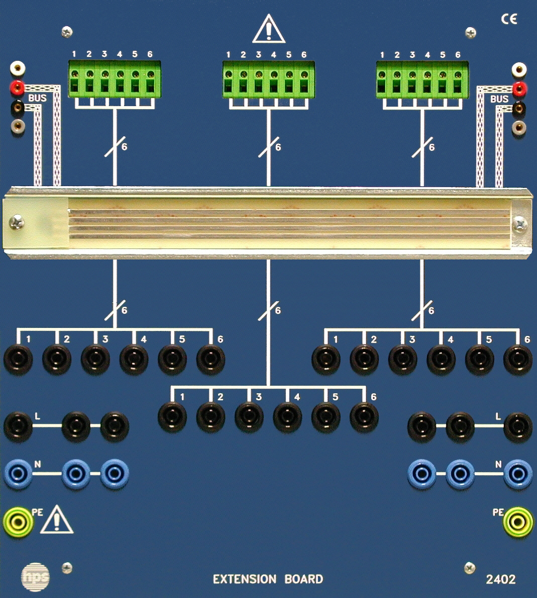
The EXTENSION BOARD Type 2402 expands hps training systems for the European Installation Bus (EIB/KNX). It accepts EIB/KNX components on a DIN rail, adapts installation wiring to 4 mm safety sockets, and includes a separate bus detector for displaying and linking bus activity.
- Extension board for hps training systems on the European Installation Bus (EIB/KNX)
- Mounting of EIB/KNX components on a DIN rail
- Adaptation of standard installation wiring to 4 mm safety sockets
- DIN rail with integrated data rail
- Multiple EXTENSION BOARDs can be interconnected
- Usable as a desktop unit or in a demonstration rack
System Setup
A DIN rail is mounted on the front of the EXTENSION BOARD. It can be fitted with standard EIB/KNX components from different manufacturers.
Three 6-pin adapters provide the transition from standard installation wiring to 4 mm safety sockets. Inputs and outputs are connected via 4 mm safety sockets, while the bus through-connection uses 2 mm sockets.
The EXTENSION BOARD can be used on a desk or suspended in a table or demonstration rack. It expands INSTALLATION BOARD Type 2401 as well as the demonstration plates for the European Installation Bus and installation technology.
- Standard EIB/KNX components for DIN rail mounting
- Accessory set Type 2402.1 with connecting leads and plugs
Bus Detector Type 2401.5
The bus detector is used in experiments with the European Installation Bus to display bus activity and to provide bus through-connection between two demonstration plates.
Bus activity can be observed via the LED. The bus detector can be inserted at any position between two demonstration plates and is powered from the bus.
- Displays bus activity via LED
- Can be inserted at any position between two demonstration plates
- Powered via the bus
- Bus detector Type 2401.5 for displaying bus activity and bus through-connection
- Board dimensions
- 266 x 297 x 110 mm (W x H x D)
- Board weight
- 1.6 kg
- Front plate
- 5 mm laminated material, matte blue, with white engraving
- Rear side
- Grey plastic enclosure for protection and desk inclination
- Required accessories
- Standard EIB/KNX components for DIN rail mounting; accessory set Type 2402.1 consisting of connecting leads and plugs
- Bus detector voltage and current
- 29 V / 30 mA, reverse-polarity protected
- Bus detector pin plugs
- 4 pieces, diameter 2 mm, spacing 19 / 9.5 mm
- Bus detector housing dimensions
- 75 x 56 x 35 mm (W x D x H)
- Bus detector weight
- approx. 50 g
- 1 Technology of the European Installation Bus (EIB)1
- 1.1 Areas of application of the EIB / KNX1
- 1.2 Topology2
- 1.3 Power supply and line lengths4
- 1.4 Communication within the EIB system4
- 1.4.1 Transmission technique4
- 1.4.2 Bus users4
- 1.4.3 Bus access methods5
- 1.4.4 Telegram structure6
- 1.4.5 Transmission time9
- 1.4.6 Byte structure within a telegram9
- 1.5 EIB components used in the manual10
- 1.5.1 Pushbutton sensors10
- 1.5.2 Bus couplers10
- 1.5.3 Chokes10
- 1.5.4 Data interface10
- 1.5.5 Binary inputs11
- 1.5.6 Binary outputs11
- 1.5.7 Twilight detectors11
- 2 The EIB Tool Software ETS213
- 2.1 System requirements13
- 2.2 Software installation13
- 2.2.1 Installation under Windows 3.1x14
- 2.2.2 Installation under Windows 95 and 9814
- 2.3 Working with ETS214
- 2.3.1 Starting and ending ETS214
- 2.3.2 ETS2 main menu14
- 2.3.3 ETS2 assistant15
- 2.3.4 Popup menus16
- 3 Safety instructions for handling the system17
- 4 Experiments with switching off19
- Experiment 1: Switching off with switch19
- Experiment 2: Switching off with switch and pushbutton28
- Experiment 3: Switching off with 4-fold pushbutton sensor29
- Experiment 4: Switching off with central off, pushbutton and 4-fold pushbutton sensor30
- 5 Experiments with two-way circuit33
- Experiment 1: Two-way circuit with two switches33
- Experiment 2: Two-way circuit with two switches and double pushbutton35
- Experiment 3: Two-way circuit with 4-fold pushbutton sensor and double pushbutton36
- 6 Experiments with intermediate and surge current circuits37
- Experiment 1: Intermediate circuit37
- Experiment 2: Surge current circuit39
- 7 Experiments with brightness control41
- Experiment: Simulation of a twilight detector41
- 8 Test and error diagnosis of EIB/KNX projects43
- 8.1 Checking physical addresses43
- 8.2 Inquiry of device information44
- 8.3 Reading the bus device memory45
- 8.4 Diagnosis of group addresses45
- 8.5 Recording EIB/KNX telegrams46
- Solutions
- Experiments with switching offS 1
- Experiments with two-way circuitS 13
- Experiments with intermediate and surge current circuitsS 23
- Experiments with brightness controlS 29
- AppendixA 1
- AbbreviationsA 1
- Planning helpA 2